Since the likes of Digital Foundry and My Life in Gaming have all been kinda CRT-crazy recently, I used the christmas holidays and the corresponding family visits to dig out an old Philips CRT TV to hook up an original SNES (as well as a PS1 and PS2) with RGB SCART.
4:3 CRT RGB gaming fun foiled by 16:9-by-default aspect ratio
The picture looked great, but the TV defaulted to a 16:9 aspect ratio, squeezing the 4:3 picture in a super weird way. The remote control of the TV had a aspect ratio control button that could toggle between the different modes (squeeze to 16:9, 4:3 and "zoomed 4:3", which seems to stretch a 4:3 image verticall a bit). However, the (replacement) remote control that was used with the TV didn't have this button (the volume and channel selection buttons on the remote worked).
Fun fact: The RF-modulated (channel 3) output was actually displayed in 4:3 by that particular TV set all the time, but RF looked really really bad compared to the crystal clear RGB output.
The back side of the TV revealed its model number: 25PT4458/01. Thankfully the Philips website still has lots of details about the TV online, including a photo of the stock remote control, as well as information about the SCART inputs (it has two SCART inputs, but only Ext1 can do RGB, Ext2 seems to only do S-Video, both can do Composite Video, too). Also, "NTSC" there suggests it can do NTSC video (60 Hz) in addition to the European-native PAL format.
Further research revealed that the remote control I'm looking for has the model number RC19039001, and replacement models come in at around 6-10 EUR on eBay and Amazon.
But of course, one wants to have the fix Right Now, and I recently did some Arduino projects, maybe there's something that can be done there?
Infrared Remote Codes
Further online investigation revealed that the IR protocol used is most likely the RC6 IR protocol and its predecessor, the RC5 protocol, which was developed by Philips.
More research brought up Marcel Majoor's
28PW9525 Remote Control documentation
that suggests the "Picture Format" button is RC6 0 245 (this did not
work for me, but it might be that the library can't deal with codes
beyond 7 bit values -- I didn't bother to check, as another code worked).
It also has a list of additional codes that are not on remote controls,
but that might be understood by Philips TVs for Power On, AV input
selection and picture format selection (presumably so that configuration
of these parameters can be automated in some applications).
Another page (Diskrete IR Codes für TV-Fernbedienungen, German language) also has these aspect ratio codes, so at least there's lots of codes to try with the TV.
Obtaining an IR LED
I didn't have IR LEDs in my toolbox, but my search around the house for the real TV remote (which ended up unsuccessful) turned up some remote controls of SCART DVB-S sat receiver boxes that we don't have in the household anymore, so I decided to take one apart and desolder the IR led from it to use in my small project.
Just like with the SUN Type 5 USB adapter, holding on to some broken scrap components can turn out to be useful for getting components off of them and not having to wait for mail-order parts to arrive.
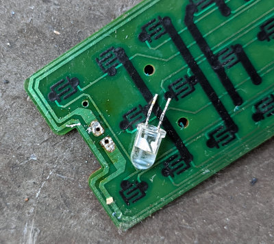
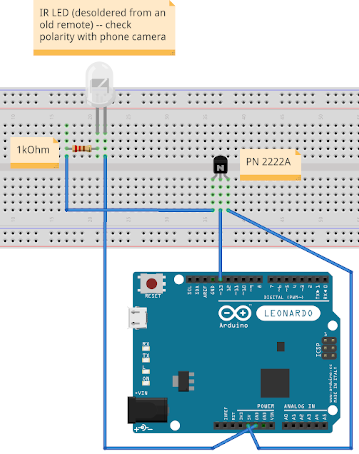
In order to check the polarity, I hooked up the LED to the 3V + GND pins (in series with a resistor) and used the phone camera to check if the IR LED lights up to determine which pin to connect to GND in the finished circuit.
Circuit
After some googling, I learned that feeding the IR LED directly from the PWM pin 13 didn't work properly, so I found Daniel Ziegler's Universalfernbedienung mit einem Arduino UNO/MEGA oder ESP8266 (in German) where he used a 2N2222 bipolar junction transistor. I based my circuit on his schematics, but also added a resistor into the mix to avoid burning out the LED (as long as it's bright enough to be detected by the TV if I hold it in front of its IR receiver, it should be fine).
Arduino IR Library
Now with some IR codes to try and the necessary components, the next
step was to find Arduino libraries
to send those RC5/RC6 codes. A quick search found
Infrared4Arduino,
which can be found as "Infrared by Bengt Martensson 1.0.6" in the
Arduino Library Manager. It has a bunch of examples, and the
RC5Renderer
sketch (in Examples → Infrared → RC5Renderer after installing the library)
already sounds like something we want to use. It doesn't really come with
much information in terms of how to set up the circuit, so I had to do
some research. The documentation suggests that on Arduino Leonardo (what
I had available, since the Uno was in use at that time), Pin 9 is used,
but after some unsuccessful attempts, I looked at the code and found
that boarddefs.h sets the value for the default SEND_PIN, and for
me it was 13 for some reason.
For the record, if you don't really know what the code ends up defining
with all those #ifdefs, just #include <boarddefs.h> in your sketch
and then do a quick Serial.print(SEND_PIN) and watch the serial monitor
-- this is how I figured out it was using pin 13 on my Leonardo board.
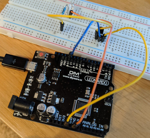
Don't mind the poor selection of jumper wire colors.
Sketch Code
I started out with the RC5Renderer example, by default it sends
the code for the "1" button on the remote. I was pretty sure that
this code should work, so I could test the circuit if it basically
works. It did (and tuned to the non-existent channel 11...). Next
up, I tried different values for the first and second parameter in
Rc5Renderer::newIrSignal() based on the pages linked above. What
worked was Rc5Renderer::newIrSignal(0, 126);, which was labeled
in one of the docs as "Picture size Superzoom" (note that it says
"RC5 3 126" in the docs, but I still needed to pass in 0 as the
first paramater -- another reliable trial'n'error result..).
// Philips TV "aspect ratio" control
// 2019-12-30 Thomas Perl <thp.io>

// 99% of the code is from the "RC5Renderer" example
// Dependency: "Infrared" by Bengt Martensson 1.0.6

#include <Rc5Renderer.h>
#include <IrSenderPwm.h>

IrSender *sender;

void setup() {
    // On my Arduino Leonardo board, PWM output is on Pin 13
    sender = IrSenderPwm::getInstance(true);
}

void loop() {
    // Picture size Superzoom  RC5 3 126
    // https://www.majority.nl/tv_28pw9525_remote_control.htm

    // This is based on the "RC5Renderer" example, but the called
    // code actually does a "new" object allocation, I don't care
    // about that here, since the sketch is run for a few seconds
    // when I power the Arduino and point the IR LED at the TV,
    // but if you build something more sophisticated, you might
    // want to just keep two copies of IrSignal (one with T=0,
    // the other with T=1) around instead of new'ing objects

    const IrSignal *signal = Rc5Renderer::newIrSignal(0, 126);
    sender->sendIrSignal(*signal);
    delay(1000);

    signal = Rc5Renderer::newIrSignal(0, 126);
    sender->sendIrSignal(*signal);
    delay(1000);
}
Putting it all together
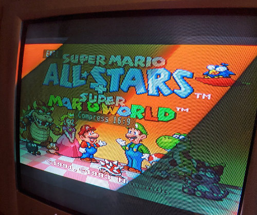
Finally with the sketch uploaded to the Arduino, and powering the Arduino via USB, it powers up and starts sending the button press every second, I hold the IR LED close to the TV's receiver and wait for it to cycle between "16:9", "4:3" and "ZOOM", some games work best in 4:3, others in zoomed in mode, here's the Super Mario All-Stars + Super Mario World SNES cartridge running in its full 4:3 glory on the CRT TV:
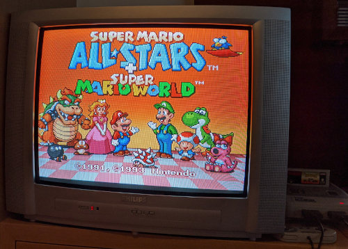
Ready for some 4:3 goomba-stomping action